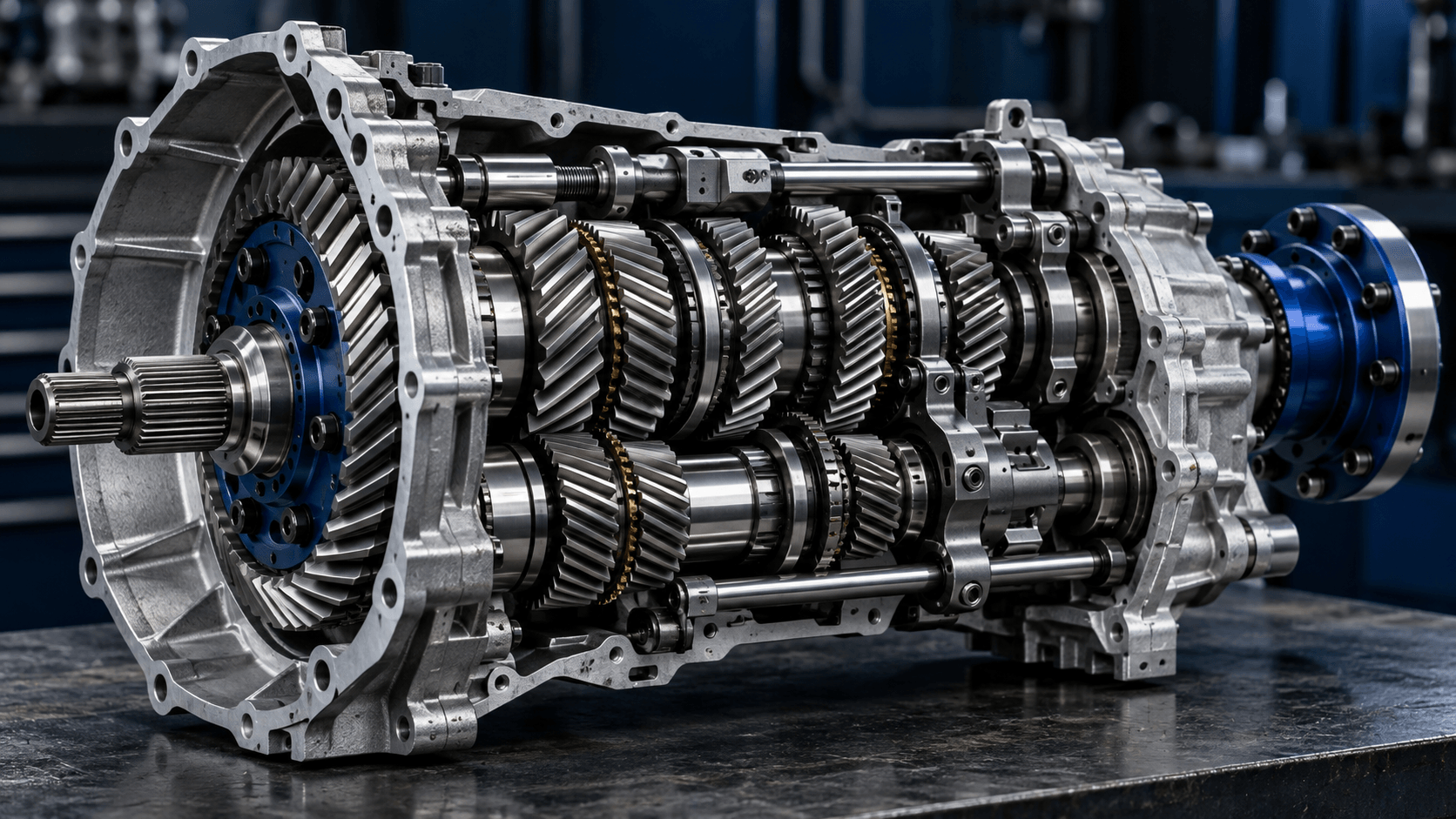
Choose a steady measurement window
Use engine RPM and an independent road-speed measurement with known tire circumference. Avoid shifts, clutch engagement and changing converter conditions. Repeat at several steady speeds; consistent inferred ratios support the interpretation, while variation suggests measurement error, slip or variable gearing.
R = engine RPM × circumference(m) / (60 × road speed(m/s))Follow the worked comparison below for the input units and assumptions.
Work through an example
At 3,600 rpm, 30 MPH and a 13-inch nominal tire, inferred overall reduction is approximately 4.64:1. A larger assumed tire circumference would produce a larger inferred ratio from the same RPM and speed.
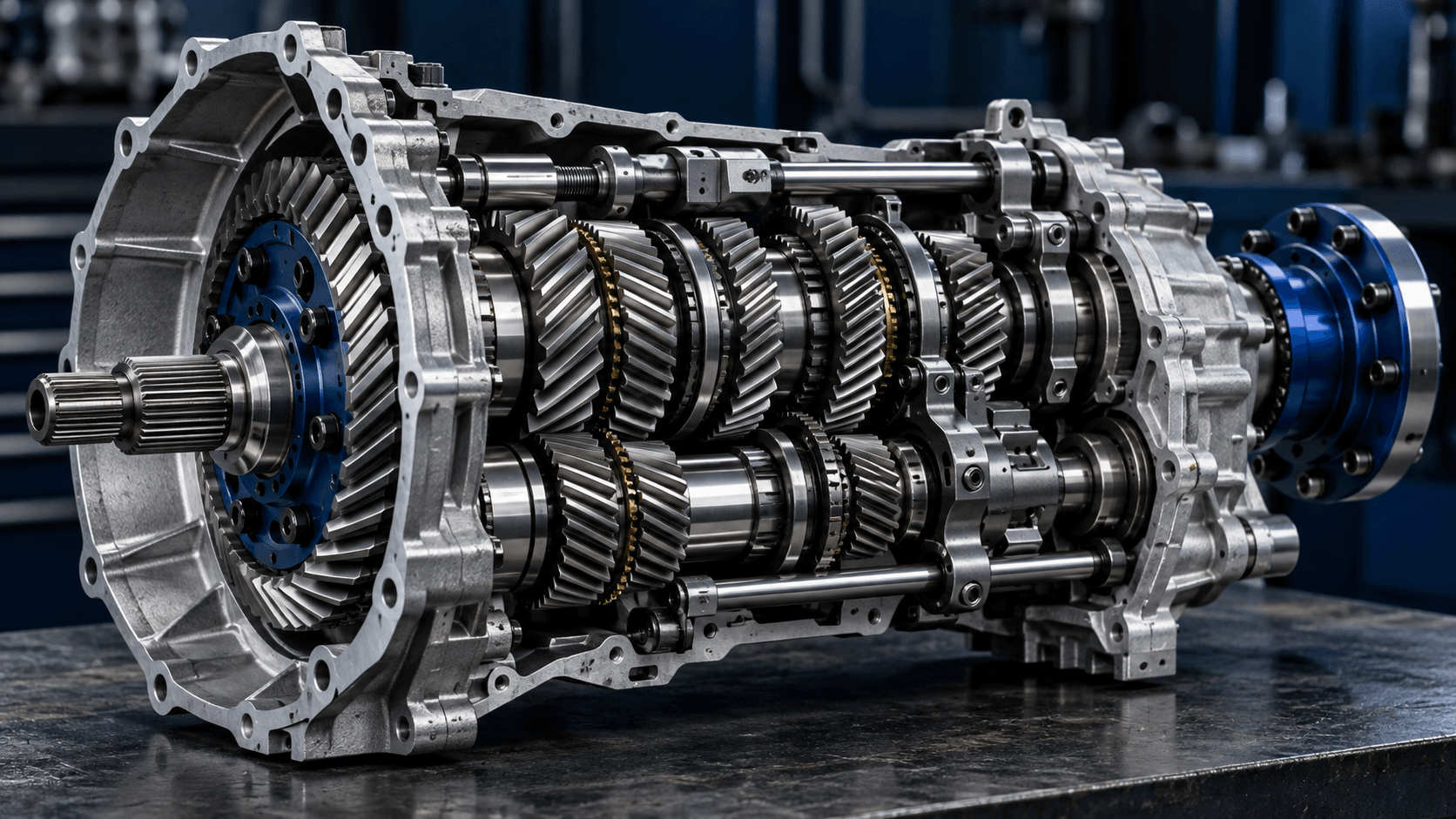
Keep speed measurement independent of drivetrain rotation
A speed display derived from the same shaft sensor may already assume a tire circumference and gear relationship. Using it to infer that relationship can reproduce the calibration assumption. An independent road-speed measurement makes the comparison more meaningful.
Repeat the calculation at several steady speeds
A fixed mechanical ratio should give similar inferred reductions when the same tire dimensions apply. Large changes suggest varying gearing, slip, unsynchronized inputs or measurement error. The result is overall reduction, not automatically the final axle ratio.
Infer overall reduction from synchronized measurements
Hold engine RPM at 3,600 and nominal diameter at 13 inches, then compare different independently measured road speeds. At the same engine speed, a higher road speed implies a smaller reduction under the no-slip fixed-ratio model.
R = engine RPM × circumference(m) / (60 × road speed(m/s))- Record engine RPM and independent road speed together at a steady operating point.
- Convert road speed into meters per second and circumference into meters.
- Rearrange the wheel-travel relationship to calculate overall reduction.
- Repeat at other steady operating points to check consistency before interpreting a result as a fixed mechanical ratio.
| Road speed (MPH) | Engine RPM | Inferred overall reduction (:1) |
|---|---|---|
| 25 | 3600 | 5.569 |
| 30 | 3600 | 4.641 |
| 35 | 3600 | 3.978 |
The inferred quotient contains every stage between the measured engine shaft and the driven wheel. It cannot identify final drive by itself if primary and gearbox reductions are unknown. A changing result can indicate a variable converter, slip, tire measurement error or unsynchronized readings, rather than a changing fixed gear set.
Check the inputs before interpreting a difference
If the displayed road speed already derives from drivetrain rotation and an assumed circumference, the input may not provide independent evidence. State the speed measurement method and avoid reading RPM and speed at different moments during acceleration.
Before you apply the result
A speedometer calibrated from drivetrain rotation may not be independent evidence after a gearing or tire change. The result includes primary and transmission reduction; it does not isolate a final axle ratio without further information.
Try the calculation
Enter your own values in the related calculators. Compare one input at a time and keep units and operating conditions visible with the result.
Frequently asked questions
Can I calculate final drive from RPM and MPH alone?
You also need rolling circumference and the other reduction stages to separate final drive from total engine-to-wheel reduction.
Why does a larger assumed tire increase inferred ratio?
For the same measured speed, a larger circumference implies fewer wheel revolutions. The engine-to-wheel RPM quotient therefore becomes larger.
Should I measure during a shift?
No. Use a steady operating point with the selected gear engaged and record RPM and speed together.
Why do repeated RPM-and-speed measurements give different gear ratios?
Check synchronized timing, rolling circumference and the selected gear first. Converter ratio change, clutch slip, wheelspin or measurement error can also make the fixed-ratio inference inconsistent.
Reference and method
Angular speed and tangential speed. Gear reductions follow tooth engagement and conservation of rotation count.
OpenStax — University Physics: rotation with constant angular acceleration ↗These explanations and examples describe the documented model. No manufacturer testing, named expert authorship or independent professional review is claimed. Read the method policy or report a correction.